
Digital Multimeter Symbols Explained: A Beginner’s Guide for DIYers
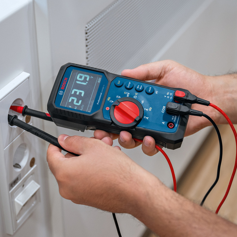
Key Findings: Multimeter Symbols at a Glance
What is the symbol for AC voltage?
The symbol for an alternating current (AC) voltage is a capital V with a wavy line (tilde) either above or next to it (V~). This symbol is only for measuring household mains power, such as wall sockets and light switches.
What is the symbol for DC voltage?
The symbol for Direct Current (DC) voltage is a capital V with a solid line and a dotted line underneath it (V⎓). Use this symbol when testing batteries, automotive electrical systems, and low-voltage electronics.
What does the Ω symbol mean on a multimeter?
Ohms is the unit of measure for electrical resistance and is represented by the Greek letter Omega (Ω). This mode allows you to measure how resistant a component or length of wire is to the flow of electrical current.
What is the continuity symbol, and what does it do?
The continuity symbol is a bunch of sound waves ()))) or a small speaker icon. In this setting, the multimeter will beep if the two testing probes have a continuous electrical path between them.
Introduction
The electrical aisle can be intimidating to the beginner, as can looking on the internet for testing equipment. The modern diagnostic tool is covered in a dizzying array of dials, ports and cryptic symbols that resemble an ancient alphabet more than a helpful user interface. But knowing these symbols is the first step to safely and successfully diagnose electrical faults in and around your home, garage or workshop.
Whether you’re trying to diagnose why your car won’t start, wiring a new light fixture, or simply checking to see if a drawer full of AA batteries is dead, a digital multimeter kit is the ultimate diagnostic tool for the job. This vital gadget lets you “see” what’s going on inside a circuit, rather than guessing in the dark and replacing expensive parts.
Simply comprehending the shorthand codes is the key to tapping into the power of a modern digital multimeter. Each symbol on the middle dial tells the internal computer what to measure, from voltage and current to resistance and continuity. This comprehensive beginner’s guide will decode the dial, explaining exactly what each symbol means, where to plug your probe leads and how to safely operate your multi metre without blowing internal fuses.
Decoding the Dial: The Primary Voltage Symbols
The biggest mistake beginners make is to confuse alternating current with direct current. If you select the wrong voltage setting, you will get an inaccurate reading (usually showing as zero), and you could also blow a cheaper multi metre.
Alternating Current Voltage (ACV or V~)
Alternating current (AC) is the electricity that comes from the national grid and goes into the wall sockets in your home. The “alternating” part refers to the fact that the electrical current is rapidly switching directions back and forth.
- The Symbol is a capital V with a wavy line (a tilde: ~). On some older or budget-friendly models, the voltage might just be written as ACV or VAC.
- When to Use it: When troubleshooting household mains power, set your multimeter to AC Voltage. The range includes wall sockets (around 230V to 240V in the UK), ceiling light fittings, electric ovens and appliances hardwired into the home.
- Safety Warning: AC mains voltage is lethal. Always ensure that your device is rated for the voltage you are testing and never touch the metal ends of the testing probes when they are live.
Direct Current Voltage (DCV or V⎓)
Direct Current (DC) flows in one steady direction. This is the kind of power that batteries, solar panels and your car’s alternator create.
- The Symbol: Look for a capital V with a solid horizontal line and a dashed line directly beneath it (V⎓). Some meters may refer to this as DCV or VDC.
- When to Use It: The DC Voltage setting is for automotive diagnostics (testing a 12V car battery), checking AA or AAA household batteries, testing laptop chargers, and tinkering with low-voltage hobby electronics.
Millivolts (mV)
You may see a special mV setting on auto-ranging multimeters. This is for millivolts ( one thousandth of a volt ).
- The Symbol: mV with either a wavy line for AC or a solid/dashed line for DC.
- When to Use: This setting is very sensitive and is used almost exclusively for complex circuit board diagnostics, testing delicate sensors, and repairing small electronics where standard voltage settings would not allow for enough decimal precision.
Measuring Resistance and Continuity
The voltage settings read the electrical pressure pushing through a circuit. The resistance and continuity settings are used to check the physical integrity of the wires and components themselves. Crucially, continuity and resistance tests must always be carried out on dead circuits with the power fully switched off.
Resistance (Ohms / Ω)
Resistance is a measurement of how much the component opposes the free flow of electrical current.
- The Symbol: The Greek letter Omega (Ω) is the symbol of resistance.
- How it Works: When you set your digital multimeter to Ohms, it uses its own internal battery to send a tiny, harmless electrical charge through the component you are testing. The screen will tell you how much resistance that charge encountered along the way.
- Reading Interpretation: A zero (0.00) reading means zero ohms of resistance. The electricity is flowing perfectly. A high number means big resistance (like passing through a heating element or resistor). If the screen says OL (Open Loop), the resistance is infinite. That means the wire is totally broken and the electricity can’t go through.
Continuity ())) )
Resistance is closely related to continuity but is much faster for simple ‘yes or no’ diagnostics. It simply tells you if an electrical path is continuous or broken.
- The Symbol: The continuity setting is represented by a series of cascading brackets that resemble sound waves ()))) or a small speaker icon.
- How It Works: Place the probes at either end of the wire, and the multi metre will immediately emit a loud beep if the wire is intact and the circuit is closed. If the wire is broken, the fuse is blown, or the switch is turned off, you will hear nothing.
- When to Use: This is most likely the most useful function for home DIYers. The continuity beep is great for a quick check to see if a household fuse has blown, to trace which wire goes where in a bundled cable, or to check that a light switch is really opening and closing the circuit.
Measuring Current (Amps, Milliamps, and Microamps)
It is a little more to it and a little more dangerous than measuring voltage. Measuring electrical current (amperage): to measure current, the multimeter tester has to be in the circuit itself. You can’t just touch the probes in parallel across a battery; the circuit has to be broken and the meter put in series so the electricity goes through the device.
- Amperage (A): A capital A, sometimes with the AC wavy line (A) or the DC solid/dashed line (A). This setting measures the passage of electricity through a circuit.
- Milliamps (mA): One thousandth of an amp. Milliamps (mA) are used for testing smaller electronic circuits and parasitic draws on automobiles.
- Microamps (µA): One millionth of an amp. The Greek letter Mu (µ) looks like a lowercase ‘u’ with a long front tail. This setting is only for ultra-sensitive electronics and certain HVAC flame sensor testing.
Probes and Ports: Avoiding the Most Common Mistake
Even if you choose the correct symbol on the central dial, if you plug the test leads into the wrong ports, your multi metre will not work properly (and could be destroyed). A typical digital multimeter has a black probe and a red probe. It usually has three or four input jacks on its bottom panel.
- COM Port (Common): The ground or negative return port. Your black probe will always live in this port. This is true no matter what test you are doing.
- VΩmA Port (Voltage / Ohms / Milliamps): This is the main input jack for your red probe. This port will be used for 95% of your daily DIY. As the letters indicate, it is used for testing voltage (V), resistance (Ω), continuity, and small currents (mA).
- The 10A Port (High Amperage): This port is only for measuring high current volumes (up to 10 amps). If you are testing the current draw of a large automotive component or heavy-duty circuit, you will need to move the red probe to this particular port. Caution: If you leave the red probe in the 10A port and try to measure the voltage of a car battery, you will instantly create a dead short, blowing the internal fuse of the meter and possibly destroying the tool.
Understanding CAT Safety Ratings
If you look at multi metres, you will see that they have different Roman numeral categories (CAT I, CAT II, CAT III or CAT IV). These ratings measure how much electrical ‘transient overvoltage’ (big, sudden voltage spikes) the metre can withstand without blowing up in your hands.
- CAT I: Only rated for low-voltage electronic work protected by transformers (e.g., laptops, hobby electronics).
- CAT II: Suitable for testing single-phase, receptacle-connected loads (plug-in household appliances, televisions, standard wall sockets).
- CAT III: Required for fixed building installations, distribution boards, heavy-duty three-phase motors and commercial lighting circuits.
- CAT IV: Highest level of safety. It is used for testing main supply lines and as a source for low-voltage building installations and external underground utility connections.
A good CAT II or CAT III rated digital multimeter is a great balance between accuracy and safety for the average home DIYer and automotive enthusiast.
Conclusion
Understanding the symbols on a digital multimeter turns a confusing plastic box into a valuable troubleshooting tool. You can tackle household and automotive electrical issues with complete confidence if you remember the difference between AC and DC voltage symbols, use the audible continuity function to trace broken wires, and make sure your probe leads are plugged into the correct safety ports.
Before starting your next DIY project, make sure your diagnostic equipment is up to the task. Using an old, uncalibrated analogue metre or a cheap device with frayed test leads poses a significant safety risk. Upgrade your toolkit by browsing our extensive selection of highly accurate, professional-grade diagnostic tools to find the ideal multimeter tester for your workshop today.
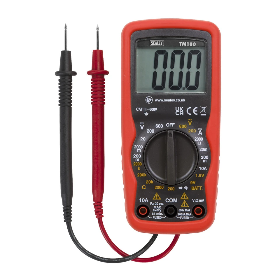
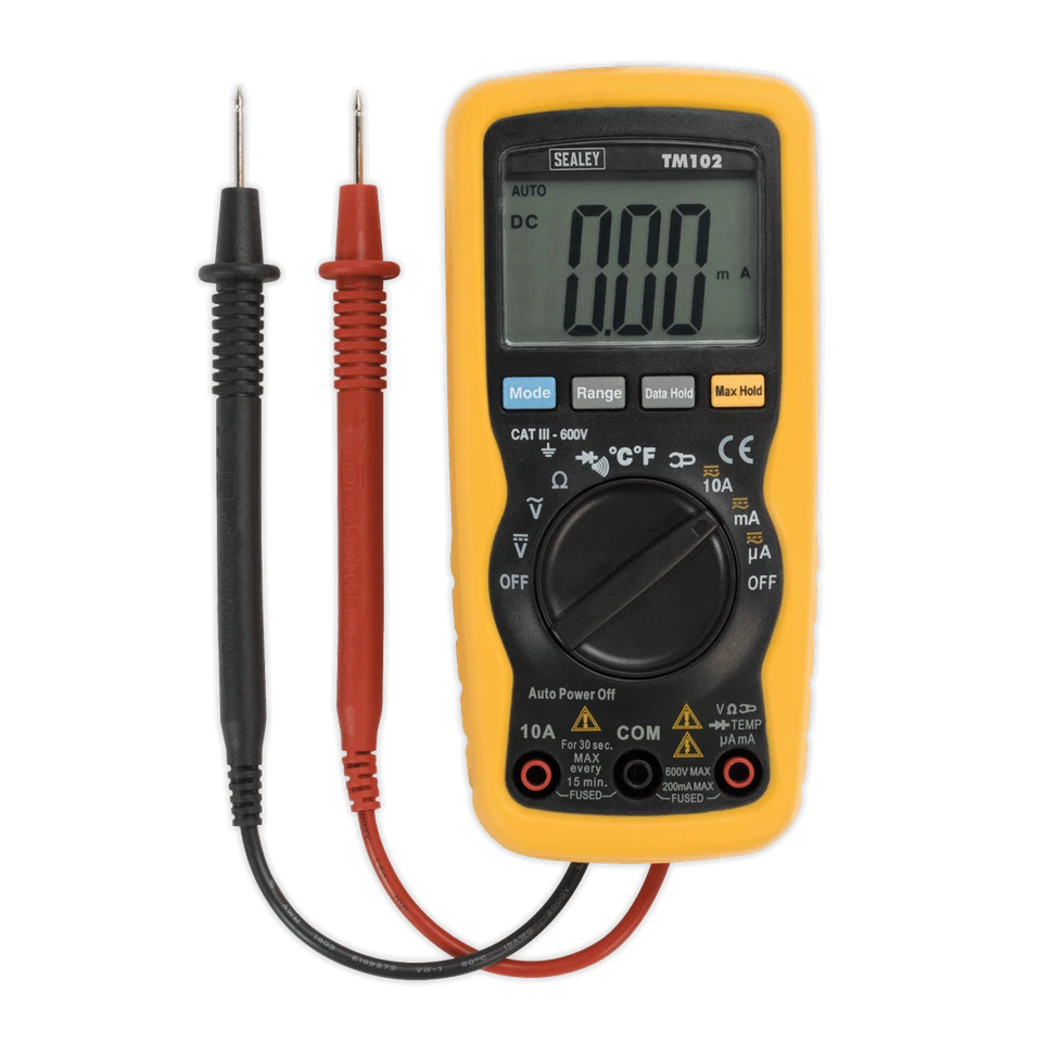
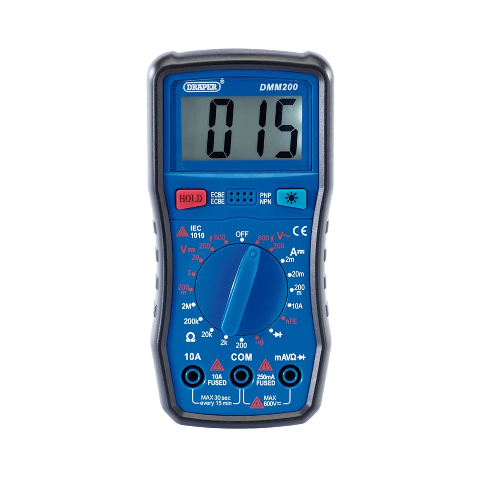
Toolden’s Multimeter Top Picks
FAQs
What does the diode symbol (an arrow pointing at a vertical line) do?
The diode symbol (->|-) allows you to test diodes, which are electronic components that act as one-way valves for electricity. The multimeter applies a small voltage to the component to ensure that electricity flows freely in one direction but is completely blocked from flowing backwards. This is an important diagnostic function when repairing printed circuit boards or testing an automotive alternator’s rectifier bridge.
What does the capacitance symbol (-| |-) mean?
The capacitance symbol resembles two vertical lines separated by a gap (-| |-). It is used to test capacitors, which are electrical energy storage components found in HVAC systems, electric motors, and microwave ovens. Because large capacitors can store lethal amounts of voltage even when unplugged, testing them safely necessitates specialised knowledge and meticulous discharge procedures.
Why does my digital multimeter display “OL” when I test a wire?
When measuring resistance (Ohms) or continuity, the letters OL stand for “Open Loop” (or sometimes “Over Limit”). This simply indicates that the multimeter cannot detect a complete path between the red and black probes. The electrical loop is fully open. This usually indicates that the wire you are testing has snapped, a fuse has blown, or a switch has been turned to the “off” position.
Do I need an auto-ranging or a manual-ranging multimeter?
An auto-ranging digital multimeter is highly recommended for first-time users and DIY enthusiasts. On a manual metre, you must guess the approximate voltage of the circuit and turn the dial to the appropriate decimal range (2V, 20V, or 200V). An auto-ranging metre eliminates this guesswork. Simply turn the dial to the general “Voltage” symbol, and the internal computer will calculate and select the ideal decimal scale for the most accurate reading.
Can a standard multimeter tester handle both household and automotive tasks?
Yes, absolutely. A standard digital multimeter can handle both environments as long as it is set to AC Voltage (for household mains) and DC Voltage (for 12V automotive systems). Simply ensure that the device has a minimum safety rating of CAT II for household use, and always store the tool in a dry location to prevent moisture from corroding the internal circuitry.
Need some help with your order? Our new help centre has a wide range of helpful articles and guides to assist you!
If you have any additional queries, please do not hesitate to contact us below: